Nexcom NISE50 Mounting and Setup
Introduction
This document will describe the general information about installation and configuration of the Nexcom NISE50 devices.
Revision history
Version | Date | Author | Comments |
1.0 | 26/09/2017 | Jacobo Eraso | Initial version |
|
|
|
|
Platform Description
Powered by the latest generation of Intel® Atom™ processor E3826 (formerly codenamed "Bay Trail-I"), NISE 50 series positions at the intelligent IoT gateway for factory automation and for smart city applications. Up to 4G on-board DDR3L memory, the NISE 50 series support operating temperature from -5 up to 55 degree C with 24V DC input with +/-20% range. The NISE 50 series have strong connectivity - Ethernet-based LAN port and traditional RS485, mainly for Modbus TCP or Modbus RTU communication.
CPU | Onboard Intel® Atom™ processor E3826 dual core, 1.46GHz |
Main Memory | On-board 2GB DDR3L 1066/1333 RAM |
| - Un-buffered and non-ECC |
| - Max up to 4GB for option |
Display Option | 1 x HDMI display |
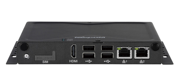
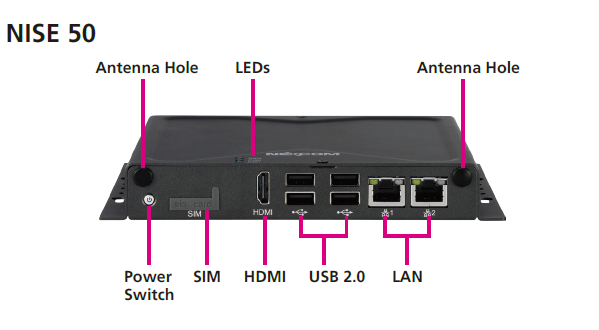
I/O Interface-Front | ATX power on/off switch1 x Storage/2 x GPO Programmable LED1 x SIM Card holder2 x Intel® I210AT GbE LAN ports; Support WoL, Teaming and PXE1 x HDMI Display Output4 x USB 2.0 (500mA per each)2 x Antenna Holes for optional Wi-Fi/3.5G antenna |
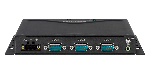
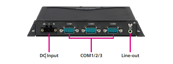
I/O Interface-Rear | 3 x DB9 for COM1 & COM2 & COM3 |
| - COM1: full RS232 signal |
| - COM2: RS232, only support Tx/Rx/GND |
| - COM3: RS422/485 auto flow control |
Storage Device | On-board 36GB EMMC / Optional mSATA module |
Expansion Slot | 3 x Mini-PCIe socket for optional Wi-Fi/3.5G modules |
| - Mini-PCIe: CN5; Size: Full; USB: V; PCIe:N/A; mSATA: Support; 3.5G/4G: Support |
| - Mini-PCIe: CN6; Size: Full; USB: V; PCIe:V; mSATA: N/A; 3.5G/4G: Support |
| - Mini-PCIe: CN7; Size: Half; USB: V; PCIe:V; mSATA: N/A; 3.5G/4G: N/A |
Power Requirements | Power input: 24V DC +/-20%1 x optional 24V, 60W power adapter |
Dimensions | 162mm(W) x 26mm(H) x 150mm(D) without wall-mount bracket |
Construction | Metal Chassis with fanless design |
Environment | Operating Temperature: |
| Ambient with air flow: -5°C to 55°C |
| (According to IEC60068-2-1, IEC60068-2-2, IEC60068-2-14)Storage Temperature: -20°C to 75°CRelative Humidity: 10% to 95% (non-Condensing)Shock Protection: |
| - mSATA / EMMC: 50G, half sine, 11ms, IEC60068-27Vibration protection w/mSATA or EMMC condition: |
| - Random: 2Grms @ 5~500 Hz, IEC60068-2-64 |
| - Sinusoidal: 2Grms @ 5~500 Hz, IEC60068-2-6 |
Certifications | CEFCC Class AUL/cUL |
General Installation Overview
The steps to fully install and configure the platform are described in the following sections, but in general the following tasks are needed:
- Prepare an installation USB: All the software installation (OS and SiteController) will be done using a usb drive. This steps only needs to be done once, to create the installation USB. Then that installation USB can be used as many times as necessary to set up as many devices as needed.
- Install the modem and antennas (options): The Nexcom NISE is shipped by default without any modem or antenna. If needed, the modem an antenna have to be installed.
- Install the software: Using the installation USB, install the Operating System and SiteController. The procedure is to turn off the device, plug the USB, turn on the device, wait until it turns off by itself, take out the USB, and turn on the device again.
- Configure the software: Connect to the device and configure the software according to the customer needs.
Installation USB preparation
All the software, including Operating System and azeti SiteController will be installed using a USB Stick. This USB Stick can be used to set up multiple devices, so this steps only need to be done once. The capacity of the USB stick used has to be equal or bigger than the size indicated by azeti for the used image.
- Download and install the program HDDRawCopy from a Windows PC.
http://hddguru.com/software/HDD-Raw-Copy-Tool/
- Get from azeti the appropriate software image (a .imgc file)
- Open HDD Raw Copy.
- Click on FILE
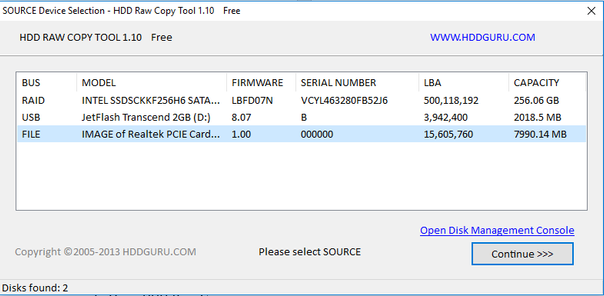
- Select the .imgc file and click open
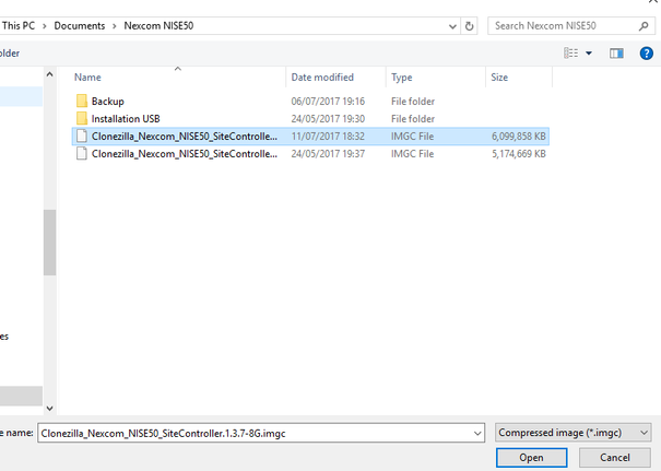
- Click "Continue >>>"
- Select the USB drive where the file will be written
WARNING: All the contents of the USB will be overwritten and lost.
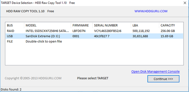
- Click "Continue >>>"
- Review the source and target, and click "Start"
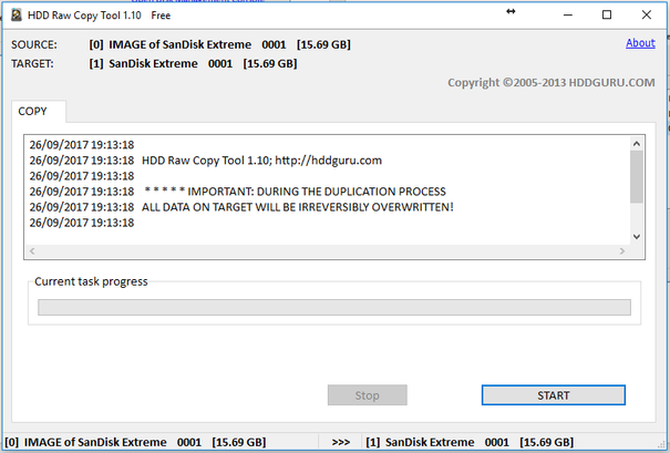
- Once the copy finishes (it may take a few minutes) check that there were no errors and unplug the USB. The USB drive will be then ready to use.
WARNING: When booting any device using this USB, it will automatically overwrite anything on the device (Nexcom Nise50, PC, etc.).
Device Installation
Modem Installation
Before You Begin
- Ensure you have a stable, clean working environment. Dust and dirt can get into components and cause a malfunction. Use containers to keep small components separated.
- Adequate lighting and proper tools can prevent you from accidentally damaging the internal components. Most of the procedures that follow require only a few simple tools, including the following:
- A Philips screwdriver
- A flat-tipped screwdriver
- A set of jewelers screwdrivers
- A grounding strap
- An anti-static pad
- Using your fingers can disconnect most of the connections. It is recommended that you do not use needle-nosed pliers to disconnect connections as these can damage the soft metal or plastic parts of the connectors.
- Before working on internal components, make sure that the power is off. Ground yourself before touching any internal components, by touching a metal object. Static electricity can damage many of the electronic components. Humid environments tend to have less static electricity than dry environments. A grounding strap is warranted whenever danger of static electricity exists.
Precautions
Computer components and electronic circuit boards can be damaged by discharges of static electricity. Working on computers that are still connected to a power supply can be extremely dangerous.
Follow the guidelines below to avoid damage to your computer or yourself:
- Always disconnect the unit from the power outlet whenever you are working inside the case.
- If possible, wear a grounded wrist strap when you are working inside the computer case. Alternatively, discharge any static electricity by touching the bare metal chassis of the unit case, or the bare metal body of any other grounded appliance.
- Hold electronic circuit boards by the edges only. Do not touch the components on the board unless it is necessary to do so. Don't flex or stress the circuit board.
- Leave all components inside the static-proof packaging that they shipped with until they are ready for installation.
- Use correct screws and do not over tighten screws.
In the case the modem and antennas need to me installed, do the following:
- Remove the chassis cover
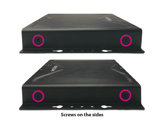
- Remove the six mounting screws around the chassis cover. There are two screws each on the top and on the sides.
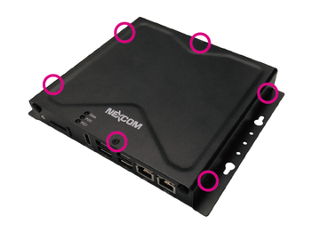
- With the screws removed, lift up the cover and remove it from the chassis.
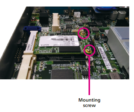
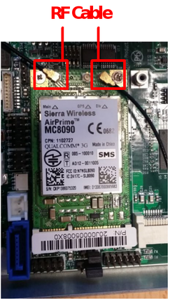
- Install the modem on the middle mini pcie slot. It is important that it is installed on the correct slot (see picture)
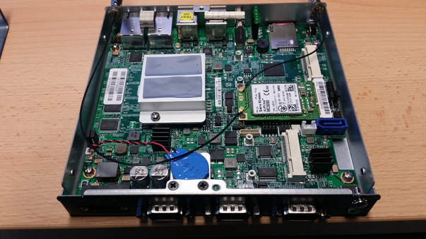
- Locate the mini-PCI Express slot (CN5) on the board.
- Insert the Wi-Fi module into the mini-PCI Express slot at a 45 degree angle until the gold-plated connector on the edge of the module completely disappears inside the slot.
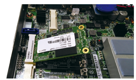
- Push the module down and then secure it with mounting screws.
- Install two antennas:
Note: Please remove the gaskets (ring 1 and ring 2) on the SMA antenna jack first.
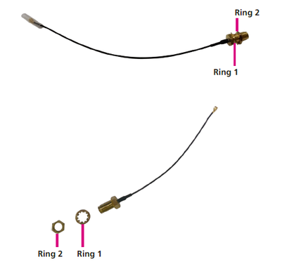
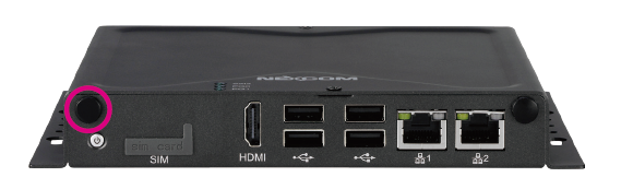
- Remove the antenna hole cover located on the front panel.
- Insert the SMA antenna jack end of the cable through the antenna hole, and insert the 2 rings (ring 1 and ring 2) back to the antenna jack.
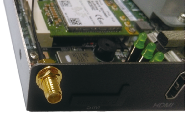
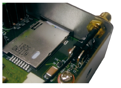
- Attach the RF cable onto the module.
- Connect the external antenna to the antenna jack.
- Put the chassis cover back on the device and the screws.
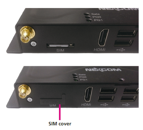
- Install the SIM card (if needed)
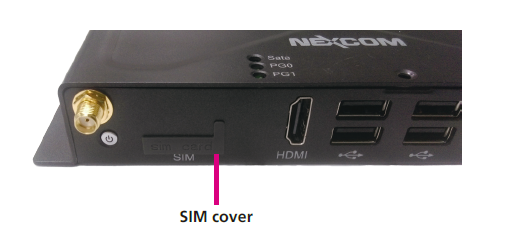
- Locate the SIM card slot on the front panel and remove the slot cover.
- Insert the SIM card into the slot.
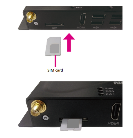
- Insert the SIM card cover back to its original position.
Software Installation
To install the software, the USB stick prepared before will be used. The steps are:
- Make sure the gateway is powered down
- Put the USB in any of the USB ports of the device
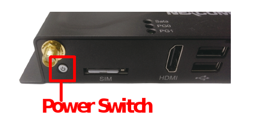
- Power on the device
- Wait until the devices is shutdown automatically. It may take a few minutes. The Power Switch button will turn red
- Remove the USB stick
- After that, the unit will be ready. The OS and SiteController will be installed, so it can be powered on.
Software configuration
To change the default configuration, connect the device. This can be done in one of the following ways:
- ssh to the device on the ethernet port 2 (10.0.0.1)
- Use a null modem cable to COM1 (baudrate 115200)
- Connect a keyboard and screen directly to the device
The default credentials are the same in all cases: azeti/azeti.
Once logged in to the device, the changes needed are:
- Set the site serial (name)
- Edit the SiteController configuration (in privileged mode)
sudo vi /opt/azeti/SiteController/config/SiteController.cfg
- In General, set the serial
[General]
# Allowed characters for the serial are upper and lower case ASCII [a-zA-Z],
# digits [0-9], dashes - and underlines _ only!
serial = Nexcom_Master
- Check in External configuration that the host, organizationShortName, user_id and password are correct.
- Save and exit (if using vi press :x)
Default configurations
- Ethernet Port 1: DHCP
- Ethernet Port 2: Static
- IP 10.0.0.1
- Network 255.255.255.0
- Serial COM1 : Console baudrate 115200
- Username : azeti
- Password : azeti