Sensor Configuration from Scratch
Introduction
azeti provides a range of predefined components and templates to choose for existing sensors and I/O devices. In case you are using sensor hardware that isn't yet included you have to create a sensor configuration from scratch.
Examples used here
This guide assumes the example of an Advantech ADAM-6050 Modbus TCP enabled I/O Module. The azeti Social Sensor Cloud comes with pre-defined/installed components.
Specifications
- 12 digital inputs, Modbus registers 101 - 113
- 6 digital outputs, Modbus coil registers 201-207 (writing into coil 0 = OFF, 1 = ON)
- IP address 192.168.0.100
- Location named Berlin-101
Component Template
You can download the component template for this example, if you're missing it in your current installation.
Workflow
The basic work flow consists of four steps.
Workflow
Create Component Instance (CI) → Create Site Template from CI → Assign Site Template to Location → Customize Location
Detailed Workflow
- Create a Component Instance, this is a "child" of the component template and holds individual model information
- Create a Site Template, this is derived from the component and holds custom configuration such as the device parameters (e.g. Modbus address, registers), automation rules, calibration or special thresholds. A best practice is to create one site template for each location that has similar hardware sensors/devices/components installed.
- Assign the Site Template to the location (remote site)
- Customize the Location Site Template for the Location, these settings (e..g specific IP address) override the basics of the site template and are specific to one location.
Create a Component Instance
An existing component is the base of a new instance. You can use the generic Modbus TCP component as a template to create your individual instance that matches the setup of the device, e.g. number of inputs and outputs and the register settings.
Create the instance:
- Go to Config/Provisioning→ Comp. Instances.
- Click + Add button and a new view will be opened listing existing components.
- Select Generic Modbus TCP I/O Device and set the name, here ADAM-6050, for the New Instance.
- Click Add or Add and Edit button that will create new component instance and close the modal window or navigate to instance editor page.
Customize the Component Instance
Model (but not location specific) parameters such as the Modbus register for the inputs and outputs are defined in the component instance. These settings are always the same for this particular model.
Digital Inputs
- Go to Config/Provisioning→ Comp. Instances.
- Locate the instance ADAM-6050 and click Edit
- Select Toggle S/U Normal Mode to open the editable view as a super user.
- Navigate in the left hand component tree to Sensors → Digital_Input_1
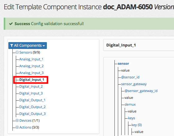
- Open in the element tree (right hand) sensor → sensors_gateway → demux → keys → key
- Set the register to 101 in the Value row and click

Repeat this step for each input and set the proper Modbus registers.
Digital Outputs / Actions
The digital outputs in our example can be switched on/off by writing a 0 (OFF) or a 1 (ON) into the coil register per output. This is a Modbus command (see step number 6).
- Go to Config/Provisioning→ Comp. Instances.
- Locate the instance ADAM-6050 and click Edit
- Select Toggle S/U Normal Mode to open the editable view as a super user.
- Navigate in the left hand component tree to Actions → Switch_Digital_Output_1
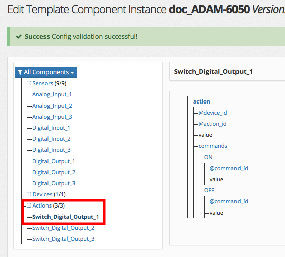
- Open in the element tree (right hand) action → commands → command → value
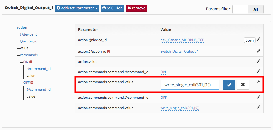
Change the command and set the appropriate register for Output 1, here it is 301. Command syntax is as follows:
write_single_coil(<Modbus_Register>, <Value>)write_single_coil(201,[1])
- Save your changes with a click on
Repeat this step for the ON and OFF command for each output (element {{action.commands.command.@command_id}}) and set the proper Modbus registers.
Create a Site Template
The previously created component instance is the base for a new site template.
Create the site template from the component instance:
- Go to Config/Provisioning → Site Templates.
- Click + Add and when modal window opens set your Name, a good practice is to set this according to your location name, here Berlin-101 and save your changes.
- From Site Templates table, find your newly created Site Template and click on the Edit button.
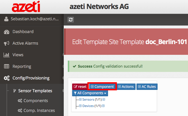
- Select Toggle S/U Normal Mode to open the editable view as a super user.
- Click + Component button, a new view opens where the base component will be selected
- Select the Instances tab and choose ADAM-6050
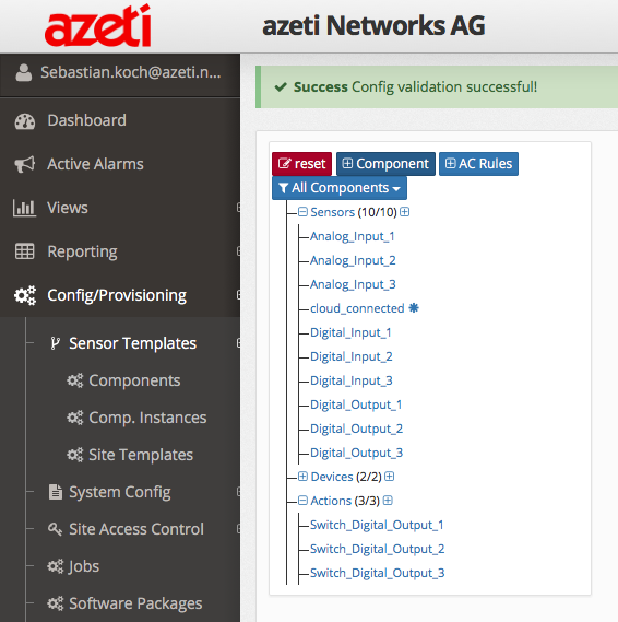
- All included objects, such as sensors or actions, are now listed. Select the ones required and click add for every input (here 12) and output (here 6) of the device.
- Select and add the Actions for your digital outputs. There will allow you to remotely switch those outputs later on (e.g. in Admin Live Table)
The new sensors and action are now listed in the tree
Assign the Site Template
After the creation of the site template it needs to be assigned for your location. The assignment won't apply any changes to your locations sensor configuration yet.
To assign a site template:
- Go to My Organization and find your location by name
- Choose Details from the right, this opens the location parameters view
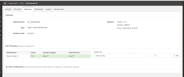
- Go to the Gatways tab
- Go to Assign New and select the correct Sensor Config in the drop down menu
- Press Save
- Click Save
Customize the Location (Site) Template
You can customize the parameters that are individual for particular sites through the Location Template, which is derived from the previously assigned Site Template. Settings like the IP address the Modbus TCP I/O module or sensor thresholds are examples for location specific settings you can configure.
For our example, we have to set the IP address 192.168.0.100 for our location.
To set the right IP address:
- Go to My Organization and click on
 (location template link)
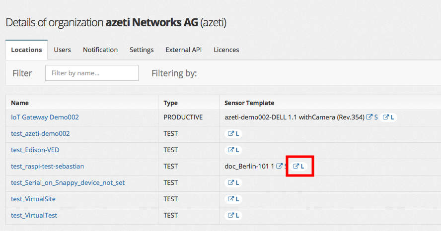
- Select Toggle S/U Normal Mode to open the editable view as a super user.
- Navigate in the left hand component tree to Devices → dev_Generic_MODBUS_TCP
- Open in the element tree (right hand) device → modbus_device → modbus_tcp → address
- Edit the address field and enter the IP address 192.168.0.100
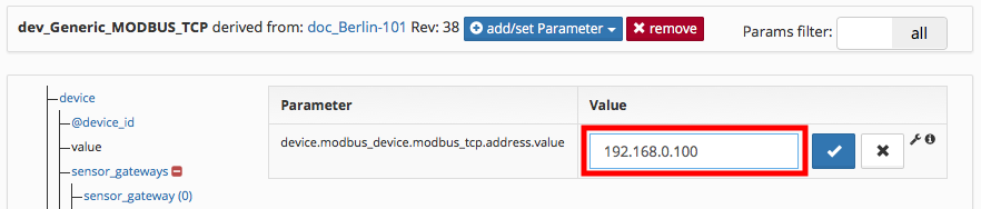
- Click to save your changes and select Toggle S/U Normal Mode to leave the super user mode.
Identifying locations with custom settings
Locations that have custom settings on top of their site template will show a differently colored location link.

Deploy the Sensor Configuration
After the configuration is done we need to deploy the configuration to our Berlin-101 location.
The deployment job for pushing a new sensor configuration must be of type config. Go to Config/Provisioning → Jobs to check the currently configured ones.
To deploy the prepared configuration:
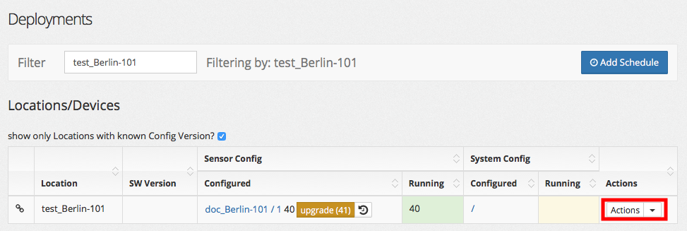
- Go to My Organization, navigate to Berlin-101 location and click
 on right hand side.
 - Click Actions → schedule which opens the deployment view
- Choose Deploy Sensor Config, and select Immediately
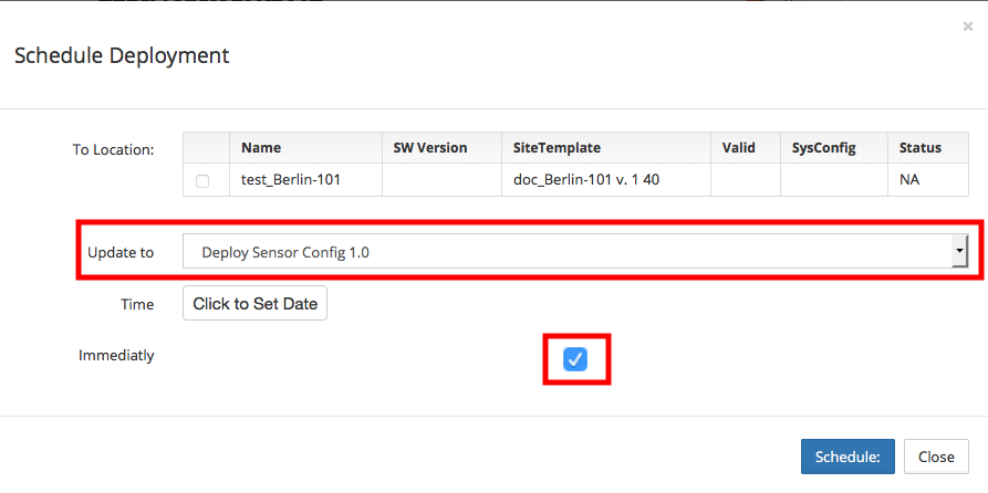
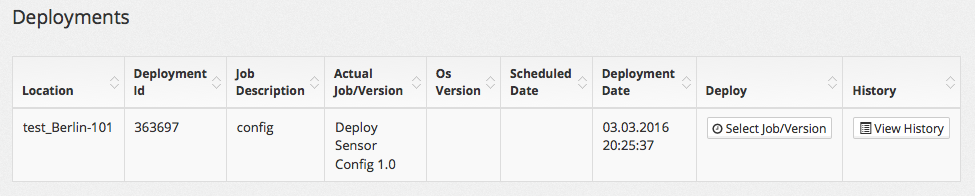
- Clicking Schedule will schedule an immediate deployment of the sensor configuration
- The deployment job will be shown in the bottom job overview
Best Practices
- Versions: Create new versions for each change if your components or site templates
- Keep Diversity Low: If possible, try to use the same ip addressing for each individual remote location, this will allow you to use one site template for many locations without any location specific customization
- Site Templates per Region: If thresholds and rules differ by region: create a new version of your base site template that holds region specific customizations, e.g. higher thresholds for temperature sensors for warmer country regions