Sensors and Devices
Introduction
The communication of the configuration between the cloud server and our Site controller is done using a XML file. This file contains information about all devices and sensors that will be connected to the Site Controller. In this guide, we will explain the main structure of the file, as well as the different labels that are used to configure the modules in Site Controller.
For your understanding, there is an Information flow, which describes how the the information flows from the sensors to the Site Controller and eventually to the Engine.
This information is provided to give you a better insight of the system and to help in troubleshooting tasks when working with a Site Controller directly. Normally you should not need to work with the files directly, as they are provided by our configuration tools.
Structure of the configuration file
The configuration file has 5 main sections to group the components configured.
Header of the file
The file start with the following header.
<?xml version="1.0" encoding="UTF-8"?>
<sensor_configuration config_version="1" schema_version="1.0">
The config_version and schema_version variables are values that indicate the version of template that we use. The config_version will be updated every time a new configuration is uploaded to the system (when we modify any sensor, device, action or gateway configuration). It is an indicative parameter and is not mandatory (you can make manual changes and republish the configuration files directly without the need of updating this value). The schema_version indicates which schema is used by the template. A change in schema will probably need a new software update to the affected modules.
We will go over them in the next pages.
<?xml version="1.0" encoding="UTF-8"?>
<component_template  config_version="1.1" schema_version="1.0">
 <description>Azeti Demo Container Kit Meeting Room</description>
 <vendor>azeti</vendor>
  <version>1.12</version>
  <class>multi sensor</class>
  	<sensors>
    	<sensor sensor_id="Name of Sensor">
		.
		</sensor>
  	</sensors>
  	<devices>
    	<device device_id="Name of Device">
 		.
    	</device>
  	</devices>
  	<actions>
    	<action action_id="Name of Action">
    	.
    	</action>
  	</actions>
  	<ac_rules>
    	<rule="Name of Rule">
		.
    	</rule>
  	</ac_rules>
</component_template>
→ Sensors
The complete sensors configuration is done between the labels <sensors></sensors>. The individual configuration for a sensor is between the labels <sensor></sensor>. Let us see one example of sensor and its configuration: the following code configures a sensor that will reflect the status of the first digital input of an ADAM-4150 device.
→ Devices
The complete devices configuration is done between the labels <devices></devices>. The individual configuration for a device is between the labels <device></device>. A device can be a physical or virtual device that gathers information. In this configuration section we define the technology that will be used, and all parameters necessary to make the device working. We define as well gateways, that will basically be the units that receive the information and bring them to the sensors.
→ Actions
Our system is capable of performing actions. Actions materialize usually in writing a register in a device, or wait some time before activating some status, sending information, etc. The possibilities of the Site Controller, with its automation controller capabilities, are endless once we configure the right actions for our modules. The complete actions configuration is done between the labels <actions></actions>. The individual configuration for a device is between the labels <action></action>.Let us copy an example of actions in order to see how they are used:
→ AC_Rules
The system is able to perform action also automated, through the use of the Automation Controller. These rules are being configured between the <rules></rules> labels.
Information flow
This section describes how the information flow from the sensors to the Site Controller, and eventually to our Cloud server. This will be illustrated with examples and diagrams that will help you understand how are the events and results flowing in the system. The diagrams pretend to illustrate a concrete flow of information, therefore in each of them we will draw and describe the main modules and topics involved outlining their role in the information flow.
Flow of information when the system start
The starting script runs all processes simultaneously. Therefore, you may expect a load peak at the moment you are starting. All modules subscribe to their corresponding configuration topics in the mosquitto broker, and wait to receive their configuration. In case the mosquitto broker was not stopped, it will have the latest valid configuration for the modules, so it will be distributed to the modules immediately. In case there is no configuration (or the configuration file has changed), the module Configuration Provider will parse the configuration and distribute the configuration to all the modules using the topic /config/module/%NameOfModule. Once a module receives its configuration, it is ready to start performing its function.
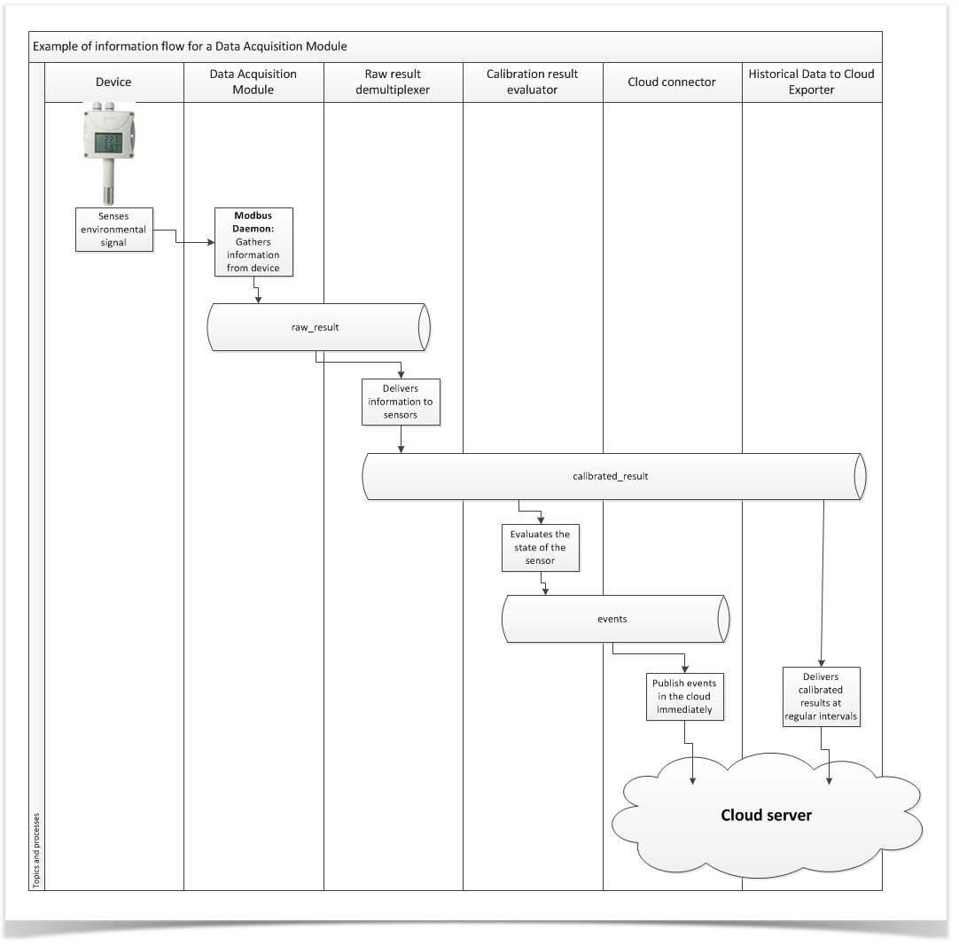
Information flow for a Data Acquisition Module
The following diagram shows how the information flows across the system, from a sensing device to the cloud server.
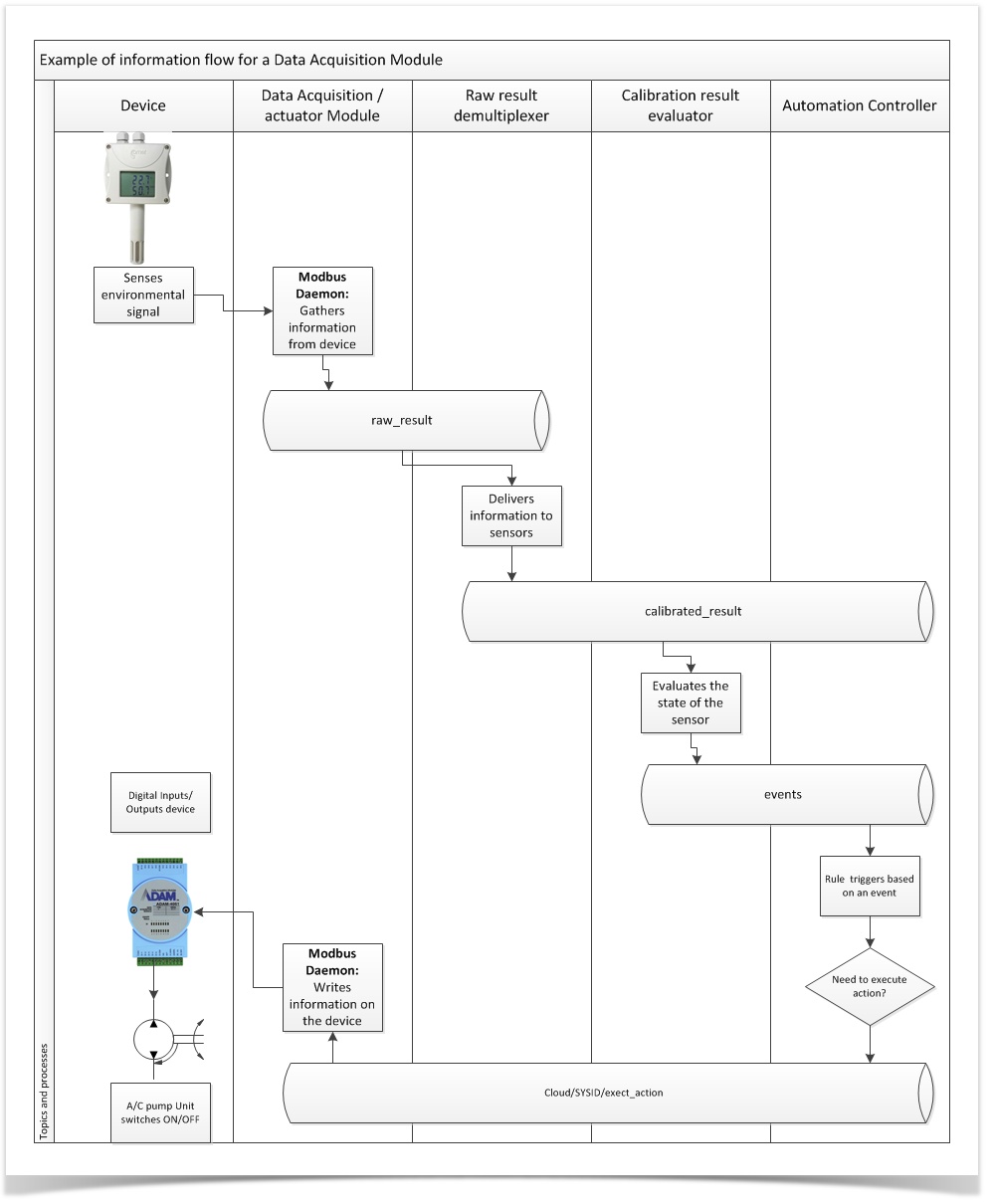
Information flow for automatic control based on parameters
This is an example of the information flow of a system configured to perform a closed loop in temperature regulation. The system senses the temperature and, based on its readings, it will activate a pump for an air conditioning device.